The Ultrasonic Metal Welding Machine is a high-precision equipment designed for welding copper sheets, aluminum busbars, and wire harness terminals. It utilizes high-frequency vibration to achieve solid-state metal bonding, with its core value lying in providing stable and reliable welding parameters and batch production efficiency. The series covers a power range from 3000W to 12000W, with a weldable cross-sectional area of 35-120mm² (e.g., YN-D2012-G), meeting the stringent quality requirements of energy storage and automotive wire harness applications.
Ultrasonic metal welding machine copper sheet welding parameters are the core process system determining the quality of copper-aluminum and other non-ferrous metal connections, encompassing key variables such as vibration frequency, welding pressure, amplitude, time, and energy control. This article is aimed at B2B procurement and engineering decision-makers, systematically elaborating on parameter windows, selection logic, and quality verification methods for equipment of different power levels, helping you achieve high-consistency, low-resistance reliable welding in scenarios such as power batteries, energy storage systems, and high-voltage wire harnesses.
Technical Architecture and Process Logic of Ultrasonic Metal Welding Machine Copper Sheet Welding Parameters
Ultrasonic metal welding machine copper sheet welding parameters are not isolated values, but a closed-loop control system determined jointly by the transducer system, horn design, and the characteristics of the material being welded. During copper sheet welding, the vibration frequency is typically fixed at 20kHz or higher, while welding pressure and amplitude must be dynamically adjusted based on the hardness, thickness, and surface condition of the copper sheet. Soft copper (such as T2 copper) has good ductility and requires relatively lower amplitude; hard copper or coated copper sheets (such as nickel-plated copper busbars) require higher pressure input to break the surface oxide film, while avoiding cracking of the copper sheet due to energy overload.
The weld cross-sectional area is the primary constraint for equipment selection. Taking energy storage copper-aluminum busbar welding as an example, copper busbars with a cross-section of 35-120mm² must use 12000W-class equipment(Fact 1), while large wire harness copper-aluminum busbars with a cross-section of 20-70mm² correspond to 8000W-class equipment(Fact 2). This correspondence stems from the energy density requirements of ultrasonic welding—insufficient power leads to an overly thin intermetallic compound (IMC) layer at the weld interface, increasing contact resistance; excessive power causes excessive plastic deformation of the copper sheet, generating micro-cracks. Therefore, the setting of ultrasonic metal welding machine copper sheet welding parameters must strictly match the equipment power class and cannot be substituted across levels.
Comparison Table of Copper Sheet Welding Parameters for Equipment of Different Power Levels
To facilitate rapid equipment matching for engineering procurement personnel, the table below summarizes the key parameter windows for each ultrasonic metal welding machine model. Data is sourced from factory technical specifications and applies to conventional copper sheet and copper-aluminum dissimilar metal welding scenarios.
| Equipment Model | Power Level | Applicable Copper Sheet Weld Cross-Sectional Area | Equipment Weight | Dimensions (mm) |
|---|
| YN-D2012-G | 12000W | 35–120mm² | 988KG | 1750×1050×2150 |
| YN-D208-G | 8000W | 20–70mm² | 957KG | 1750×1050×2150 |
| YN-D206-G | 6000W | 15–50mm² | 192KG | 1400×760×2000 |
| YN-X206-Z | 6000W | 10–50mm² | 118KG | 1020×610×1200 |
| YN-X204-Z | 4000W | 1–30mm² | 132KG | 1020×610×1200 |
| YN-P203-F | 3000W | 1–100mm² | 73KG | 565×269×442 |
| YN-X203-Y | 3000W | 0.35–20mm² | 88KG | 670×520×410 |
(Data source: (Fact 1)–7) It should be specifically noted that although the YN-P203-F has a power level of 3000W, its weld cross-sectional area covers 1–100mm²(Fact 4), making it suitable for precision electronics and sensor copper sheet welding. This indicates that power is not the sole basis for selection; horn geometric design, transducer efficiency, and frequency tracking accuracy also determine actual welding capability.
Copper Sheet Thickness and Cross-Sectional Area Matching: Selection Logic for Ultrasonic Metal Welding Machine Copper Sheet Welding Parameters
The constraint of copper sheet physical properties on ultrasonic metal welding machine copper sheet welding parameters is non-linear. For every 0.5mm increase in thickness, the required amplitude and pressure need to be increased by approximately 15%–20%, and this increment intensifies as the cross-sectional area expands. Taking the energy storage industry as an example, copper busbar connections in power battery modules typically use 2–6mm thick copper busbars with a cross-section in the 35–120mm² range. In this case, the 12000W-class YN-D2012-G(Fact 1) can provide sufficient vibration energy and rigid support, ensuring that the weld peel force reaches over 85% of the base material strength.
For large wire harness copper-aluminum busbar welding scenarios, the 8000W-class YN-D208-G(Fact 2) with its 20–70mm² welding window balances production efficiency and quality stability. Its heavier frame structure (957KG) effectively suppresses mechanical resonance during high-power welding. For high-voltage wire harness copper-aluminum terminal welding, the 6000W split-type YN-D206-G(Fact 3) is recommended. This model covers a 15–50mm² cross-sectional area, and its split structure allows the horn and generator to be installed separately, facilitating integration into robotic arms or turntable stations in automated production lines. If your copper sheet thickness exceeds 6mm or the cross-sectional area falls outside the above range, please contact our engineers to confirm a customized parameter solution.
Copper Sheet Welding Quality Verification Standards and Parameter Optimization Methods
The quality of ultrasonic metal welding machine copper sheet welding parameters ultimately needs to be verified through quantitative indicators. Procurement parties should focus on the following four quality dimensions: weld peel force (should reach over 70% of the base material tensile strength), contact resistance (should be lower than 1.2 times that of bolted connections of the same cross-section), metallographic cross-section porosity (not exceeding 2% of the weld area), and interface bonding rate (not lower than 95%). For parameter optimization, the orthogonal test method is recommended, using welding pressure, amplitude, and welding time as three factors, with peel strength as the objective function for regression analysis. Typically, convergence to the optimal window can be achieved after three rounds of iteration.
For conditions with thicker oxide layers on the copper sheet surface, welding time can be appropriately increased or a dual-stage pressure curve can be adopted—the first stage uses high pressure to break the oxide film, and the second stage uses low pressure for holding to promote atomic diffusion. It should be noted that hardness differences between different batches of copper sheets (e.g., the Vickers hardness difference between TU1 oxygen-free copper and T2 copper can reach 20HV) can cause optimal parameter shifts. It is recommended to conduct process validation using materials from the same batch before mass production. If your copper sheet material, thickness, and surface condition are not within the above parameter ranges, please provide samples, and our laboratory can issue a free ultrasonic metal welding machine copper sheet welding parameter recommendation report.
Application Scenarios of Ultrasonic Metal Welding Machine Copper Sheet Welding Parameters in the New Energy Industry
- Power Battery Module Copper Busbar Welding:Using YN-X206-Z(Fact 5) or YN-X204-Z(Fact 6), covering 10–50mm² and 1–30mm² copper sheet connections respectively, meeting the low-resistance, high-consistency welding requirements for lithium battery tabs and copper busbars. This scenario has stringent requirements for weld fatigue life, and it is recommended to control the welding time within the 0.3–0.8 second range.
- Energy Storage System Copper-Aluminum Busbar Connection:The YN-D2012-G(Fact 1) is recommended. Its 12000W power can stably weld dissimilar metal lap joints of 35–120mm² copper and aluminum busbars, with the interface IMC layer thickness controllable within 1–3μm, avoiding the formation of brittle phases.
- High-Voltage Wire Harness Copper-Aluminum Terminal Welding:The 6000W split-type YN-D206-G(Fact 3) is suitable for 15–50mm² cross-sectional areas. Its split structure supports remote control and data acquisition, making it suitable for online inspection stations in new energy vehicle high-voltage wire harnesses.
- Precision Sensors and Electronic Packaging:The YN-P203-F(Fact 4) covers an ultra-wide range of 1–100mm² with 3000W power. Combined with a 20kHz frequency, it can achieve dissimilar-thickness welding of 0.1mm thin copper foil and thick copper substrates, with a weld heat-affected zone of less than 0.5mm.
Common Process Issues and Parameter Adjustment FAQ
In ultrasonic metal welding machine copper sheet welding parameters, how should welding pressure be initially set?
The initial pressure is recommended to be set at 0.3–0.6kN per square millimeter of cross-sectional area, taking the upper limit for harder copper sheets. If weld edge warping occurs, reduce pressure and increase amplitude; if the weld center is not fused, increase pressure or extend welding time.
What is the pattern of influence of welding time on copper sheet weld strength?
Excessively short welding time (less than 0.2 seconds) leads to insufficient plastic flow at the interface, resulting in insufficient peel strength; excessively long time (greater than 1.5 seconds) may cause annealing softening of the copper sheet and grain coarsening. It is recommended to conduct gradient tests using 0.1-second steps.
How should amplitude parameters be adjusted based on copper sheet thickness?
For copper foil below 0.5mm, an amplitude of 15–20μm is recommended; for 0.5–2mm copper sheets, 20–30μm is recommended; for thick copper busbars above 2mm, 30–40μm is required. Excessively high amplitude accelerates horn surface wear, requiring simultaneous inspection of the horn material.
How should parameters be corrected when the copper sheet surface has oil contamination or oxide layers?
It is recommended to increase the welding pressure by 10%–15% and add 0.1–0.2 seconds of pre-pressure time. If the oxide layer is thick (dark oxide film), a dual-stage pressure curve can be used, or ultrasonic cleaning with alcohol can be performed first.
Why is my copper sheet contact resistance high after welding?
Possible causes include: insufficient welding energy resulting in an overly thin IMC layer, foreign matter on the contact surface between the horn and copper sheet, or incomplete destruction of the copper sheet surface coating (such as tin plating). It is recommended to check horn cleanliness and appropriately increase amplitude.
How can parameter consistency be ensured when hardness varies significantly between different batches of copper sheets?
It is recommended to conduct Vickers hardness sampling inspection for each batch of copper sheets upon incoming inspection. If the hardness deviation exceeds 10%, parameter window validation needs to be re-performed. Consider pre-setting multiple recipes in the equipment and switching by batch.
Can a 12000W equipment weld small cross-section copper sheets below 20mm²?
Not recommended. The minimum controllable energy output of a 12000W equipment may still exceed the tolerance limit of small cross-section copper sheets, causing the copper sheet to collapse. For small cross-section welding, equipment below 4000W should be selected, such as the YN-X204-Z(Fact 6).
What special requirements are there for parameter settings when welding copper-aluminum dissimilar metals?
For copper-aluminum welding, the horn should be designed biased toward the aluminum side (the softer metal), with amplitude reduced by 10%–15% compared to pure copper welding, and welding time shortened by 0.1 seconds, to avoid excessive deformation on the aluminum side producing flash.
How can it be determined whether a weld is in a cold weld or over-weld state?
Cold welding manifests as low peel force with a flat interface on the fracture surface; over-welding manifests as cracks at the copper sheet edges or a bluish weld color (high-temperature oxidation). It is recommended to perform peel testing on the first piece of each batch and record the fracture surface morphology.
Is there a difference in parameter accuracy between split-type and integrated equipment?
Split-type equipment (such as the YN-D206-G) separates the generator from the horn, increasing signal transmission distance, but the impact on 6000W-class equipment is negligible. Its advantage lies in flexible deployment in automated production lines, with parameter control accuracy identical to integrated types.
In ultrasonic metal welding machine copper sheet welding parameters, what is the function of frequency tracking?
The frequency tracking system monitors the transducer resonant frequency in real time. When horn temperature rises or load changes cause frequency drift, it automatically adjusts the output frequency to maintain amplitude stability. This is key to ensuring consistency during prolonged continuous welding.
Do welding parameters need adjustment after copper sheets are nickel-plated or silver-plated?
Yes. The coating hardness is higher than the copper substrate. It is recommended to increase pressure by 5%–10% and amplitude by 2–3μm to penetrate the coating and achieve atomic diffusion of the base metal.
Does higher equipment power always guarantee better welding quality?
Not necessarily. When power is excessive and the horn design is mismatched, energy can concentrate in local areas, producing over-burning or cracks. Equipment selection should follow the principle of "cross-sectional area matching power" rather than blindly pursuing high power.
How can the long-term stability of ultrasonic metal welding machine copper sheet welding parameters be verified?
It is recommended to conduct SPC monitoring over 1000 consecutive welds, recording the mean and standard deviation of peel force and contact resistance. If the standard deviation exceeds 5% of the mean, horn wear or transducer aging needs to be inspected.
Can your company provide free welding testing for copper sheet samples?
Yes. Please send the description of your copper sheet material, thickness, cross-sectional area, and surface condition to us. We will conduct parameter optimization testing in our laboratory using equipment of the corresponding power level and issue a test report including recommended parameters.
Certifications and Technical Support
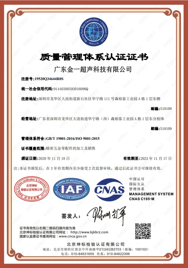
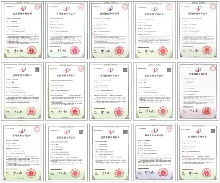
Our full range of ultrasonic metal welding machines has passed CE, FCC, and ISO 9001 quality management system certifications. Key components (transducers, horns, generators) are made of aviation-grade aluminum alloy and titanium alloy materials, ensuring reliability during long-term continuous operation. All equipment undergoes 72-hour full-load aging tests before leaving the factory, and a complete process parameter manual and operation training are provided.
If you have further questions about ultrasonic metal welding machine copper sheet welding parameters, or need customized solutions for specific copper sheet specifications, please contact our application engineering team. We provide full-process technical support from sample testing, parameter calibration, to production line integration, ensuring that the equipment achieves optimal welding quality in your production environment.