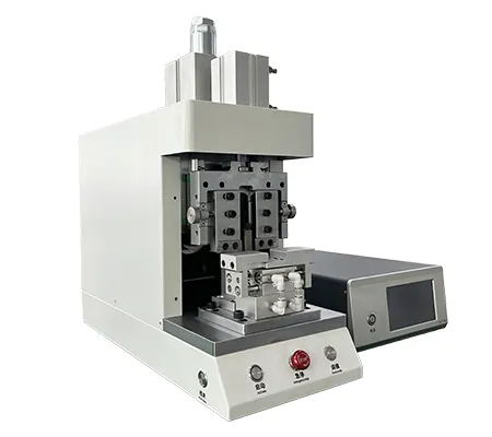
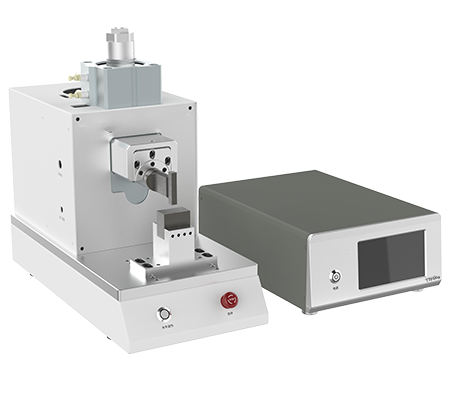
The ultrasonic metal welding machine is a high-efficiency device for welding copper and aluminum busbars, wire harness terminals, and energy storage batteries, covering a power range from 3000W to 12000W (e.g., YN-D2012-G, welding area 35-120mm²). Its core value lies in replacing traditional connections with solid-state welding technology, ensuring conductivity and reliability to meet precision manufacturing needs.
How to debug an ultrasonic metal welding machine is the key factor determining welding quality and production stability. This article provides a comprehensive professional debugging guide covering preparation, parameter setting, structural differences, precision scenarios, quality verification, and troubleshooting, helping engineering and procurement personnel establish a systematic understanding of equipment calibration to ensure optimal performance in copper-aluminum busbar energy storage welding, power battery wire harness welding, and precision electronic welding scenarios.
How to debug an ultrasonic metal welding machine: Basic equipment knowledge and pre-debugging preparation
To answer the question of how to debug an ultrasonic metal welding machine, one must first establish a basic understanding of the equipment structure and working principle. The ultrasonic metal welding machine converts high-frequency electrical energy into mechanical vibration energy through a transducer, causing plastic flow and intermolecular fusion on the metal workpiece surface under pressure. The entire process does not pass current through the workpiece, so there are no sparks or molten metal, making it particularly suitable for joining dissimilar metals such as copper and aluminum.
The following preparations must be completed before debugging; any omission may lead to distorted subsequent parameter adjustments:
- Verify equipment installation levelness and confirm fixing bolt torque to ensure overall machine rigidity stability
- Test air source pressure stability; it is recommended to equip a precision pressure reducing valve to control pressure fluctuation within ±0.1MPa
- Verify power supply voltage and phase sequence, and confirm grounding resistance complies with electrical safety regulations
- Check cleanliness of the horn, anvil, and transducer surfaces to remove oil and oxide layers
- Confirm cooling system (air-cooled/water-cooled) operating status to avoid temperature drift during prolonged welding
Equipment of different power levels and structural types has significantly different debugging focuses. For example, the debugging path for the D-series split structure differs from the X-series integrated structure; operators must execute differentiated debugging procedures according to the specific model manual. For large copper-aluminum busbar welding scenarios, equipment selection directly affects the debugging baseline. For instance, YN-D2012-G (welding area 35-120mm², weight 988KG, dimensions 1750×1050×2150mm) and YN-D208-G (welding area 20-70mm², weight 957KG, dimensions 1750×1050×2150mm) have notable differences in amplitude and pressure setting ranges.
Core parameter debugging methods and accuracy standards for ultrasonic metal welding machines
The core of how to debug an ultrasonic metal welding machine lies in the coordinated adjustment of four major parameters: welding amplitude, welding pressure, welding time, and trigger pressure. These four parameters are coupled with each other and need to be calibrated sequentially and cross-verified.
- Amplitude parameter:Set the transducer output amplitude based on welding area and material hardness, and verify by actual measurement with an amplitude meter. Insufficient amplitude causes cold welding, while excessive amplitude may cause fatigue cracks in the workpiece.
- Welding pressure:Set cylinder pressure according to workpiece thickness and lap area; pressure fluctuation should be controlled within ±0.1MPa to ensure consistent plastic deformation per weld.
- Welding time:Fine-tune based on welding strength pull test results to avoid cold welding (time too short) or over-welding (time too long causing excessive intermetallic compound growth).
- Trigger pressure:Set the critical pressure value for transducer oscillation to ensure consistent welding start point each time, avoiding start timing drift caused by workpiece height tolerances.
During debugging, the correspondence between parameters and welding quality should be recorded synchronously to establish batch process parameter cards. For different welding area ranges, equipment selection and parameter baselines can reference the following verified specifications:
- YN-D2012-G: Welding area 35-120mm², suitable for copper-aluminum busbar energy storage welding(Fact 1)
- YN-D208-G: Welding area 20-70mm², suitable for large wire harness copper-aluminum busbar welding(Fact 2)
- YN-X206-Z: Welding area 10-50mm², weight 118KG, dimensions 1020×610×1200mm, suitable for power battery wire harness welding(Fact 5)
Differentiated debugging procedures for split and integrated structures
How to debug an ultrasonic metal welding machine differs significantly across machine structures; the debugging points for split and integrated types are described separately below.
Split structure (D series) debugging points
The split structure separates the generator from the welding head assembly, requiring separate confirmation of signal cable shielding and length limits to avoid high-frequency signal attenuation or interference. Special coupling paste should be applied to the connection surface between the transducer and horn to ensure energy transmission efficiency. Taking YN-D206-G as an example (welding area 15-50mm², weight 192KG, dimensions 1400×760×2000mm), the split structure requires focused debugging of the alignment accuracy between the welding head and anvil, because the split design is more sensitive to mechanical alignment errors—any slight offset will cause uneven welding energy distribution(Fact 3).
Integrated structure (X series) debugging points
The integrated structure is compact; after resonant frequency debugging, it should be locked and marked to prevent frequency drift during subsequent operations. Taking YN-X204-Z as an example (welding area 1-30mm², weight 132KG, dimensions 1020×610×1200mm), the integrated structure requires attention to the impact of overall machine rigidity on welding consistency, because frame deformation is directly transmitted to the welding interface, resulting in uneven pressure distribution(Fact 6).
Ultrasonic metal welding machine debugging techniques for precision welding scenarios
For low-power precision welding scenarios, how to debug an ultrasonic metal welding machine requires finer energy control strategies. Precision electronics and sensor welding demand extremely high energy control accuracy; it is recommended to use energy mode instead of time mode, precisely controlling the input energy of each weld in joules.
- Taking YN-P203-F as an example (welding area 1-100mm², weight 73KG, dimensions 565×269×442mm), this model is suitable for precision electronics and sensor welding. During debugging, start at 50% baseline energy and increase incrementally by 5% each time while observing weld cross-section changes(Fact 4).
- Taking YN-X203-Y as an example (welding area 0.35-20mm², weight 88KG, dimensions 670×520×410mm), this model is suitable for high-precision metal welding. During debugging, attention should be paid to resonant point drift compensation at 20KHz frequency; frequency tracking calibration is recommended every two hours(Fact 7).
- Clamping and positioning accuracy debugging for micro-small workpieces and horn stroke fine-tuning methods: use high-precision fixtures with a dial indicator to confirm positioning repeatability within ±0.02mm, and fine-tune horn stroke in increments of 0.01mm.
Quality verification and process optimization after ultrasonic metal welding machine debugging
After debugging, a strict quality verification process must be executed to ensure the effectiveness and repeatability of parameter settings.
- Destructive welding strength testing:Pull force, peel force, and shear force test standards and acceptance criteria, executed per customer drawings or industry standards; typically, pull force should not be less than 80% of the base material strength.
- Weld cross-section metallographic analysis:Observe the uniformity of intermetallic compound distribution; the ideal welding interface should present a continuous, void-free metallurgical bonding layer.
- Sealability testing (if applicable):Air/fluid tightness test methods and standards, applicable to welding scenarios requiring sealed connections.
- Batch trial welding verification:Parameter stability monitoring under continuous production conditions; it is recommended to trial weld 200 pieces consecutively and sample-check key dimensions and strength.
- Continuous parameter optimization method based on SPC statistical process control:Monitor fluctuations in welding strength and appearance dimensions through control charts, and adjust parameter center values in a timely manner.
After debugging, a complete debugging report should be formed, including parameter set values, measured values, test results, and operator information, serving as an important part of the equipment archive for subsequent traceability and process inheritance.
Common debugging fault troubleshooting and maintenance recommendations for ultrasonic metal welding machines
The following is a summary of common abnormal phenomena, cause analysis, and elimination methods during debugging to help operators quickly locate problems.
| Abnormal phenomenon |
Possible cause |
Troubleshooting and elimination method |
| Insufficient welding strength |
Amplitude set too low, insufficient pressure, time too short |
Gradually increase amplitude and pressure, verify with pull force testing |
| Horn overheating |
Insufficient cooling system flow, excessively long continuous welding time |
Check cooling water path/air duct, increase intermittent intervals |
| Frequency detuning alarm |
Horn wear, loose transducer connection, missing coupling paste |
Reapply coupling paste and tighten connections; replace horn if necessary |
| Welding position offset |
Anvil alignment deviation, unstable workpiece clamping |
Recalibrate anvil position, optimize fixture positioning |
| Unstable trigger pressure |
Air source pressure fluctuation, cylinder seal wear |
Install precision pressure reducing valve, replace seals |
Maintenance recommendations: Check horn and anvil surface condition daily before startup, clean transducer heat sink weekly, calibrate cylinder pressure sensor and amplitude meter monthly, and perform a full machine resonant frequency retest quarterly.
Product technical specification overview
To facilitate procurement and engineering decisions, the verified technical specifications of each model in this product line are summarized below. All parameters come from factory measured data; unverified parameters should be confirmed with the manufacturer.
| Model |
Power |
Welding area |
Weight |
Dimensions (mm) |
Typical applications |
| YN-D2012-G |
12000W |
35-120mm² |
988KG |
1750×1050×2150 |
Copper-aluminum busbar energy storage welding(Fact 1) |
| YN-D208-G |
8000W |
20-70mm² |
957KG |
1750×1050×2150 |
Large wire harness copper-aluminum busbar welding(Fact 2) |
| YN-D206-G |
6000W |
15-50mm² |
192KG |
1400×760×2000 |
High-voltage wire harness copper-aluminum terminal welding(Fact 3) |
| YN-P203-F |
3000W |
1-100mm² |
73KG |
565×269×442 |
Precision electronics and sensor welding(Fact 4) |
| YN-X206-Z |
6000W |
10-50mm² |
118KG |
1020×610×1200 |
Power battery wire harness welding(Fact 5) |
| YN-X204-Z |
4000W |
1-30mm² |
132KG |
1020×610×1200 |
Lithium battery wire harness terminal welding(Fact 6) |
| YN-X203-Y |
3000W |
0.35-20mm² |
88KG |
670×520×410 |
High-precision metal welding(Fact 7) |
| JY-D204-F |
4000W/6000W/8000W |
1-35mm² |
82KG |
660×350×680 |
General metal welding(Fact 12) |
Application scenarios
The ultimate purpose of how to debug an ultrasonic metal welding machine is to serve specific production scenarios. This product line covers a complete power spectrum from precision electronics to large-scale energy storage welding, with main application scenarios including:
- New energy vehicle power battery wire harness welding:Using YN-X206-Z and YN-X204-Z, suitable for reliable connection of copper-aluminum terminals and wire harnesses, meeting vibration and temperature rise requirements.
- Energy storage system copper-aluminum busbar welding:Using YN-D2012-G, 12000W ultra-high power ensures metallurgical bonding strength of large cross-section copper-aluminum busbars.
- Precision electronics sensor welding:Using YN-P203-F and YN-X203-Y, energy mode control ensures welding consistency of micro workpieces.
- Large wire harness and high-voltage connector welding:Using YN-D208-G and YN-D206-G, split structure adapts to production line layout requirements.
FAQ: Common questions on ultrasonic metal welding machine debugging
How to debug the amplitude parameter of an ultrasonic metal welding machine?
The amplitude parameter should be set based on welding area and material hardness, and verified by actual measurement with an amplitude meter at the horn working surface. It is recommended to start at 60% of the equipment's rated amplitude and gradually increase until welding strength meets requirements. For copper-aluminum dissimilar metal welding, amplitude is typically set between 20-30μm.
What range should welding pressure fluctuation be controlled within?
Welding pressure fluctuation should be controlled within ±0.1MPa. It is recommended to install a precision pressure reducing valve and air reservoir at the air source end to reduce pressure fluctuations caused by other actuator movements in the air circuit.
How to determine the optimal welding time?
Welding time should be fine-tuned based on welding strength pull test results. Adjust in increments or decrements of 0.05 seconds each time and observe the pull force trend. When pull force reaches above 80% of base material strength with no degradation over 10 consecutive pieces, the optimal time window can be determined.
What impact does improper trigger pressure setting have?
Trigger pressure set too high causes delayed oscillation start and inconsistent welding start points; set too low may cause oscillation before the horn is fully pressed down, resulting in energy leakage. It is recommended to use the pressure corresponding to 10%-15% of workpiece thickness as the initial value, then fine-tune through trial welding.
What is the difference between split and integrated structure debugging?
The split structure requires additional attention to signal cable shielding and length limits, as well as alignment accuracy between the welding head and anvil; the integrated structure focuses more on overall machine rigidity and resonant frequency locking. Refer to the corresponding model manual for specific differences.
Why use energy mode for precision welding?
Energy mode precisely controls the input energy of each weld in joules, unaffected by grid voltage fluctuations and minor workpiece size differences, providing higher repeatability than time mode, suitable for precision electronics and sensor welding.
How to set the baseline energy when debugging YN-P203-F?
It is recommended to start at 50% baseline energy, increase by 5% each time, and observe weld cross-section changes. This model is suitable for precision electronics and sensor welding, covering a welding area of 1-100mm², and should be adjusted according to actual workpiece size.
How to compensate for frequency drift in YN-X203-Y?
YN-X203-Y operates at 20KHz; frequency tracking calibration is recommended every two hours. If frequency drift exceeds ±0.1KHz, check horn wear condition and transducer connection tightness.
How to verify welding quality after debugging?
Destructive testing (pull force, peel force, shear force), metallographic analysis (observing intermetallic compound distribution), sealability testing (if applicable), and batch trial welding verification (recommended 200 consecutive pieces) must be performed.
How to troubleshoot insufficient welding strength?
First check whether amplitude meets requirements, then confirm whether pressure is within the set range, and finally verify whether welding time is sufficient. Troubleshoot in the order of amplitude → pressure → time, adjusting only one variable at a time.
What causes horn overheating?
Horn overheating is usually caused by insufficient cooling system flow or excessively long continuous welding time. Check whether the cooling water path/air duct is clear, appropriately increase welding intermittent intervals, and reduce power output if necessary.
How to handle frequency detuning alarm?
Frequency detuning alarm is usually caused by horn wear, loose transducer connection, or missing coupling paste. Reapply special coupling paste and tighten connections; if the issue persists, replace the horn.
How to solve welding position offset?
Welding position offset is mostly caused by anvil alignment deviation or unstable workpiece clamping. Recalibrate the anvil position, optimize fixture positioning accuracy, and ensure the workpiece does not shift during the welding process.
What special precautions should be taken when debugging YN-D2012-G?
YN-D2012-G is a 12000W ultra-high power device with a welding area of 35-120mm². During debugging, special attention should be paid to cooling system heat dissipation capacity, and operators should receive specialized training. It is recommended to have factory engineers provide on-site guidance during initial debugging.
How should the equipment maintenance schedule be arranged?
Check horn and anvil surface condition daily before startup, clean transducer heat sink weekly, calibrate cylinder pressure sensor and amplitude meter monthly, and perform a full machine resonant frequency retest quarterly.
What should the debugging report include?
The debugging report should include equipment model and serial number, parameter set values, measured values, test results (pull force, metallographic photos, etc.), operator information, debugging date, and remarks, serving as an important part of the equipment archive.
Certifications and contact
All models in this product line have passed CE, FCC, and ISO 9001 quality management system certifications, ensuring compliance with international standards in electrical safety, electromagnetic compatibility, and manufacturing consistency. All equipment undergoes full-load aging tests and welding quality sampling before leaving the factory, and complete debugging manuals and process parameter databases are provided.
To obtain detailed debugging guidance or process parameter recommendations, please provide your specific welding materials, workpiece dimensions, and production capacity requirements, and our application engineers will develop a targeted debugging plan for you. For technical parameters not listed on this page, please feel free to call and confirm.
How to debug an ultrasonic metal welding machine is a systematic project that requires combining theory with practice. It is recommended to maintain close technical communication with the manufacturer during the initial stage of equipment use to jointly optimize process parameters and achieve dual assurance of welding quality and production efficiency.