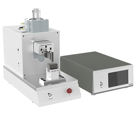
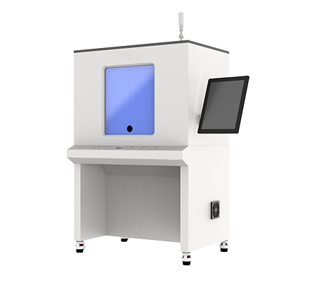
The ultrasonic metal welding machine is a precision device that achieves solid-state joining of metals such as copper and aluminum through high-frequency vibration, suitable for energy storage copper-aluminum busbars (welding area 35-120mm²) and power battery wiring harness applications. The equipment requires no auxiliary materials for debugging, and parameters can be precisely set to ensure stable welding quality and efficient delivery.
How to debug a metal ultrasonic welding machine is the key link determining welding quality and production line stability. This article provides a full-process technical debugging guide covering equipment installation, acoustic system matching, sonotrode alignment, process parameter coordination, and quality verification, helping engineering personnel systematically master the core methods from debugging to mass production.
How to debug a metal ultrasonic welding machine: Equipment installation and initial parameter settings
The first step in how to debug a metal ultrasonic welding machine begins with standardized installation and initial settings. After unboxing, the machine model and accompanying documents should first be verified to confirm that the electrical specifications match the on-site power supply. Taking the D-series flagship model YN-D2012-G as an example, its total machine weight reaches 988KG, with overall dimensions of 1750×1050×2150mm. During installation, a level gauge must be used for precise calibration of the equipment base, ensuring the four-corner level error does not exceed 0.05mm/m, to avoid uneven force on the sonotrode caused by machine tilt.
Initial parameter settings should be preset based on the welding area range. For example, YN-D208-G is suitable for copper-aluminum busbar welding of 20-70mm², with recommended initial pressure set in the 0.2-0.4MPa range; while YN-X203-Y is suitable for precision welding of 0.35-20mm², with initial pressure controlled at 0.1-0.25MPa. Before debugging, the emergency stop mechanism action verification, acoustic horn cooling system water path flow check, and ground resistance measurement (should be less than 4Ω) must be completed to ensure all safety interlock functions are normal before proceeding with subsequent acoustic system debugging.
Frequency matching debugging of ultrasonic generator and transducer system
Frequency matching is the core technical step in how to debug a metal ultrasonic welding machine. Modern ultrasonic generators have automatic frequency tracking functions. Debugging personnel should observe the deviation between the generator output frequency and the transducer resonant frequency through the device's built-in frequency scanning interface. Under normal conditions, the frequency deviation of a 20KHz system should be controlled within ±50Hz. If the deviation exceeds ±150Hz, check whether the transducer connection bolt torque meets the standard and whether the acoustic horn has cracks or deformation.
Amplitude settings should be adjusted in stages based on welding material and area. For the 3000W-class YN-X203-Y, the amplitude range is typically set at 20-35μm; while for the 12000W-class YN-D2012-G, the amplitude can be increased to 40-55μm. The power output curve linearity verification method is: under no-load conditions, gradually increase the power setting from 10% to 100%, record the actual output power, and the linearity deviation should be less than 5%. Meanwhile, by monitoring the temperature rise of the transducer after 30 minutes of continuous operation (should be below 60°C), the optimal resonance state of the acoustic system can be determined. For the split-type model YN-D206-G, due to the separated layout of generator and head, additional inspection of the shielding layer integrity of the high-frequency connection cable is required to prevent electromagnetic interference causing frequency lock loss.
Sonotrode and anvil alignment precision debugging and wear assessment
The alignment precision between the sonotrode and anvil directly determines the transmission efficiency of welding energy. In the X/Y axis directions, use a dial indicator to measure the parallelism between the sonotrode working surface and the anvil edge, requiring deviation no greater than 0.02mm. Z-axis centering adjustment should ensure that when the sonotrode presses down, the working surface fully contacts the anvil surface, with the gap controlled between 0.01-0.03mm. Concentricity calibration can be judged by applying coloring agent on the anvil surface, performing an air pressure test, and observing the uniformity of the indentation marks.
For equipment with different welding areas, alignment precision requirements vary. Small-area precision welding equipment such as YN-P203-F (welding area 1-100mm²) has the highest alignment precision requirements, with recommended alignment re-inspection every 5,000 welds; while large-area copper busbar welding equipment such as YN-D2012-G (welding area 35-120mm²), due to larger workpiece dimensions, the alignment tolerance can be appropriately relaxed to 0.05mm, but the wear condition of the sonotrode working surface still requires regular inspection. When obvious pits or cracks appear on the sonotrode working surface, repair or replacement should be performed promptly. Typically, sonotrode life is 100,000 to 200,000 welds, subject to actual operating conditions.
Coordinated debugging strategy for welding pressure, amplitude, and time
The coordinated debugging of the three welding quality elements—pressure, amplitude, and time—is the core methodology of how to debug a metal ultrasonic welding machine. For copper-copper welding, recommended pressure setting is 0.3-0.5MPa, amplitude 30-45μm, welding time 0.3-0.6 seconds; for aluminum-aluminum welding, due to the softer material, pressure should be reduced by about 20%, and amplitude can be appropriately increased; for copper-aluminum dissimilar metal welding, intermediate parameters should be adopted, with priority given to enabling the segmented amplitude control function, i.e., using low amplitude (70% of set value) in the initial welding stage for surface oxide film breaking, then switching to full amplitude to complete metal bonding.
For high-power equipment, such as the 8000W YN-D208-G and 12000W YN-D2012-G, when welding thick copper busbars (thickness 3-8mm), it is recommended to enable the pressure gradient compensation function. This function can gradually increase pressure according to a preset curve during the welding process to compensate for the contact pressure drop caused by material softening, ensuring uniform energy input at the welding interface. The peel strength test of trial weld samples is the core basis for parameter optimization. When the peel strength reaches above 80% of the base material strength, the parameter combination can be judged as qualified. If strength is insufficient, prioritize adjusting amplitude (increase or decrease 2μm each time), then adjust welding time (increase or decrease 0.05 seconds each time), and finally fine-tune pressure.
Parameter adaptation debugging for different welding areas and workpiece structures
Different welding area ranges require differentiated parameter adaptation logic. For small-area precision welding (0.35-20mm²), YN-X203-Y or YN-P203-F is recommended. These devices have fast response speeds and are suitable for thin-wall workpieces such as electronic sensors and precision terminals. Debugging should use a combination of low pressure (0.1-0.2MPa), short time (0.1-0.3 seconds), medium amplitude (25-35μm), paired with a fine anvil to control indentation depth.
For medium-area welding (15-50mm²), YN-X206-Z or YN-D206-G can be selected, suitable for power battery connecting strips, high-voltage wiring harness terminals, etc. Recommended pressure setting is 0.25-0.4MPa, welding time 0.3-0.5 seconds, amplitude 30-40μm. For large-area copper-aluminum busbar welding (35-120mm²), YN-D2012-G or YN-D208-G should be selected. These devices have good rigidity and large power margin, with pressure that can be increased to 0.4-0.6MPa, welding time extended to 0.5-0.8 seconds, and amplitude reaching 40-50μm to ensure energy penetration through thick cross-sections. For copper-aluminum transition busbar structures, double-sided welding process is recommended, and positioning grooves should be designed on the anvil to ensure workpiece clamping consistency.
Welding quality inspection and debugging effectiveness verification standards
Systematic quality verification must be performed after debugging is completed. Visual inspection standards include: indentation depth should be controlled within 10%-15% of the base material thickness, flash width not exceeding 1.5mm, and the welding area surface free of cracks and excessive oxidation discoloration. In destructive testing, tensile testing is the most common method. For a 20mm² welding area, the qualified tensile value should not be lower than 800N; for 50mm² area, not lower than 2000N; for 120mm² area, not lower than 4500N. Peel testing is suitable for thin plate welding, requiring the welding interface to exhibit ductile fracture rather than brittle peeling after peeling. Cross-section metallographic analysis can observe the metal bonding rate at the welding interface, with the qualified standard being a bonded area ratio greater than 90%.
Online monitoring methods include welding energy curve recording and height drop tracking. The energy curve should show a smooth rise followed by a plateau characteristic. If sudden energy drops or fluctuations occur, it indicates acoustic system or parameter anomalies. The height drop (displacement of the sonotrode from contact to stop) should be controlled within the 0.1-0.3mm range. Excessive values indicate excessive pressure or amplitude, while insufficient values indicate inadequate energy input. It is recommended to establish a traceability archive of debugging parameters and quality data for each device, recording the reason, result, and corresponding quality inspection data for each parameter adjustment, providing data support for parameter consolidation and continuous optimization in mass production.
Common debugging fault troubleshooting and maintenance points
The following summarizes high-frequency issues and solutions encountered during metal ultrasonic welding machine debugging, presented in Q&A format.
How to troubleshoot insufficient welding strength?
First check whether the amplitude setting is too low, try increasing by 2μm each time; second, confirm whether the welding time is too short, gradually extend by 0.05 seconds; third, check whether the pressure is insufficient, appropriately increase by 0.05MPa. If the above adjustments are ineffective, check the sonotrode and anvil alignment precision, and whether the sonotrode working surface is excessively worn.
What causes sonotrode overheating?
Sonotrode overheating is usually caused by acoustic system detuning. Check whether the transducer connection bolt torque meets the standard, whether the acoustic horn has cracks, and whether the generator frequency has drifted. Additionally, blocked cooling water paths or insufficient flow can also cause overheating; check the cooling system operating status.
How to handle frequency lock loss?
Frequency lock loss is mostly caused by transducer or acoustic horn damage, poor connection cable contact, or internal parameter drift in the generator. First check all connection points of the acoustic system, then use an impedance analyzer to measure the transducer resonant frequency. If the deviation exceeds ±200Hz, the transducer or acoustic horn needs to be replaced.
How to solve excessive welding splash?
Excessive splash is usually caused by excessive amplitude or insufficient pressure. Reduce the amplitude setting value while appropriately increasing pressure to ensure tight contact at the welding interface. Additionally, check whether the workpiece surface is clean; oil contamination or oxide layers can aggravate splash.
What causes parameter drift?
Parameter drift is commonly seen after ambient temperature changes or prolonged equipment operation. Temperature rise can cause the acoustic system resonant frequency to shift. It is recommended to preheat the equipment for 10 minutes before precision welding. Also, regularly calibrate the pressure sensor and displacement sensor.
How to select between YN-D2012-G and YN-D208-G?
YN-D2012-G is the 12000W flagship model with a welding area of 35-120mm², suitable for energy storage copper busbars and large aluminum busbars; YN-D208-G is the 8000W model with a welding area of 20-70mm², suitable for large wiring harness copper-aluminum busbars. The selection basis is the workpiece cross-sectional area and material thickness.
What is the difference in debugging between split-type and integrated equipment?
For split-type equipment (such as YN-D206-G), the generator and head are separated, requiring additional inspection of high-frequency cable length and shielding performance, with attention to signal attenuation issues during debugging. Integrated equipment has a compact structure and is relatively simpler to debug, but has limited heat dissipation space, requiring attention to temperature rise during prolonged operation.
How to ensure alignment precision of precision welding equipment?
For precision welding equipment (such as YN-P203-F), it is recommended to use optical centering auxiliary tools and regularly perform alignment verification using standard sample blocks. After each sonotrode or anvil replacement, three-axis centering adjustment must be performed again.
What to do when the welding area exceeds the equipment range?
When the welding area exceeds the equipment's rated range, use beyond the rated range is not recommended. The appropriate model should be selected based on the actual welding area. If the welding area exceeds 120mm², consult the manufacturer for custom higher-power equipment or adopt a multi-pass welding process.
How to extend sonotrode service life?
Regularly clean the sonotrode working surface to avoid metal chip accumulation; control amplitude within the recommended range to avoid overload operation; check working surface wear after each weld and promptly repair minor damage. A comprehensive inspection is recommended every 20,000 welds.
What is the maintenance frequency for the pneumatic system?
The air filter element is recommended to be replaced every 3 months, and the pneumatic triple unit should be drained of accumulated water weekly. If the air source has high moisture content, drying equipment should be added to prevent moisture from entering the cylinder and affecting pressure stability.
What is the equipment ground resistance requirement?
The equipment ground resistance should be less than 4Ω to ensure operational safety and acoustic system stability. It is recommended to measure ground resistance every six months and check whether the ground wire connection is secure.
How to analyze abnormal fluctuations in the welding energy curve?
Energy curve fluctuations may be caused by inconsistent workpiece surface conditions, sonotrode wear, or pressure fluctuations. First check the consistency of incoming workpieces, then check the sonotrode condition, and finally confirm whether the air source pressure is stable.
How to establish a parameter traceability archive?
It is recommended to use electronic management software to record the date, operator, adjustment content, trial weld results, and final confirmed parameters for each parameter adjustment. Also save corresponding quality inspection data to form a complete parameter-quality correlation database.
What should be noted when restarting equipment after prolonged shutdown?
After prolonged shutdown, first check whether the pneumatic and water paths are clear and whether electrical connections are loose. After power-on, first perform 10 minutes of no-load operation, observe the frequency tracking status and temperature rise, then perform trial welding verification.
Certifications and Contact
This series of ultrasonic metal welding machines has passed CE, FCC, and ISO9001 quality management system certifications. Key models (such as YN-X203-Y) have complete product certification documents. All equipment undergoes 72-hour continuous aging tests and full parameter calibration before leaving the factory to ensure performance consistency of delivered equipment. We provide full-cycle technical support from equipment selection, process debugging to after-sales maintenance. Delivery cycles are confirmed based on model and order quantity, with regular models available in stock.
For detailed equipment technical parameter sheets, process debugging manuals, or sample welding testing services, please contact our application engineering team. Based on your specific workpiece material and welding area requirements, we will provide customized parameter debugging solutions and equipment selection recommendations to ensure optimal welding quality on your production line.